In order to make the our Home on Wheels more versatile we needed to do
some electrical upgrades to the coach.
As it was delivered to us is just fine for some folks,
but we prefer not to stay in RV parks and other crowded places.
We prefer the freedom to camp when and where we want.
Often that means in the middle of nowhere, and that means no electricity.
While we are in the middle of nowhere however, we still like/need our creature comforts...
Satellite TV, Microwave, Computers and office equipment.
My ability to work from the camper demands a constant power source.
Some folks solve that problem with a generator.
We don't like that option for many reasons.
To be truly self sufficient off the Grid you need a source of power...
Batteries can fill that need.. day or night.
But you also need a way to change the Direct Current
that batteries provide to Household AC Current if you want to
be really be able to live comfortably.
that batteries provide to Household AC Current if you want to
be really be able to live comfortably.
An Inverter does that.
Lastly you need a way to keep those batteries charged
A generator - or SOLAR POWER are two possibilities.
Not being a fan of generators Solar was the way for us.
Not being a fan of generators Solar was the way for us.
My quest for solar power began a couple of years ago.
First I did a ton of research.
There are many great blogs and other internet sources of info for adding solar to an RV.
My Montana RV group plus the RV Net website have lots of resources and
gives you the ability to connect to people who have done what you are contemplating.
That can save you having to reinvent the wheel.
While I was designing my system, there was some groundwork
that could be done in order to get ready.
I needed to upgrade my battery system as the single 12v battery
that was supplied with the coach was not going to cut it.
that was supplied with the coach was not going to cut it.
I also knew that I would need to upgrade the battery cabling and add some distribution
posts that the solar system and inverter would tie into.
So Phase I of the install was do both of those things.
4 Deep-cycle 6v 240 amp-hour Batteries were installed.
2 each wired in series to provide 12v 240 amp hours,
then the two series strings wired in parallel to provide 480 ah at 12v
Below are the batteries and the enclosure to vent the gasses from charging.


What might look like a mass of Spaghetti is really fairly organized.
This picture was taken while work was in progress so some covers on the posts and fuse
block are not in place but would be under normal circumstances.
One of the components that I consider crucial in a good design is some
form of Energy Monitor.... Think of it as a sophisticated
fuel gauge for your battery bank.
So Phase I of the install included the installation of a TriMetric 2025

This device tells you how much energy you have pulled out of your battery bank,
how much you have put back in the bank, how much energy remains in
the bank, how much energy you are currently pulling out and so forth.
Once installed you can turn on appliances and watch the gauge. It will tell you
how much load each item draws.
The last item in Phase I was a temporary install of a 600W inverter that was in our last
5th wheel. It would give me enough AC power to run my office equipment for the time being.
After Phase I was complete we took off for 2 1/2 months and traveled 10,000 miles.
That was our trip this year you read about earlier.
By having the Trimetric installed we were able to accurately measure our power
requirements in real world use. This aided in our final refinement of our design
in order to make sure that our solar capacity would take care of our
power requirements. Battery recharging on this trip was handled by our
portable generator and visits to campgrounds with electricity.
Upon our return I got fully into the final design considerations.
After making all my decisions and reading all of the installation manuals
I drew out an electrical schematic of all the parts,
and how they would fit (wire) together in the final plan.

A first big decision in the design and upon which much of the rest of
the design hinges is whether or not to use a subpanel in the design.
You can wire the inverter directly to the main panel, and then the inverter could power all
loads in the coach - you will be responsible for not using items (such as Air Conditioning)
that would overwhelm it when running on Inverter.
Although it is more work, I decided to go the subpanel route. That was the method
recommended by most of the experts as the preferred install, plus I'd rather not worry
about forgetting to turn off the Air Conditioner when we leave an electrified location
only to find our batteries dead when we arrive at our next location.
This way the Inverter will only supply power to loads on the sub panel.
First I had to pull out the existing AC Load Center and remove the circuits that I
wanted to move over to the sub panel.


The sub panel I installed is capable of accepting up to 8 circuits or 120amps.
I selected 5 circuits that I wanted to be able to power from the Inverter.
These included most of the wall outlets, the microwave and the Fridge.
While I don't normally plan to run the fridge off of the batteries, I wanted
to include it just in case I ran out of propane while boondocking.
After the sub panel was installed, I installed the Inverter.

It was installed in the "Basement" area of the RV.
At 2000w continuous it will power all of the loads that we need.
Next was installing the equipment necessary to harvest power from the solar panels.
Solar panels are dependent on energy from the Sun,
and as you know - the sun can be bright
or dim. That means you can have a lot of power or not so much.
A solar controller is an automatic device which receives the power
produced by the panels and passes it along to the batteries at a proper voltage
that will keep the batteries happy.
The controller is the device on the right.


One hole is for the display that monitors the Controller, the other for the Inverter.
I mounted the displays and then waited for a good weather window
to get up on the roof and lay down the panels.
As luck would have it - Sat night a cold front passsed thru and
Sunday morning dawned cloudy and cool. Perfect!
So Kate and I climbed up top and go to work.


Throwing the switch!
I threw the breakers and my controller lit up and Voila...
We began harvesting energy from the Sun!
All systems are go!

4 Deep-cycle 6v 240 amp-hour Batteries were installed.
2 each wired in series to provide 12v 240 amp hours,
then the two series strings wired in parallel to provide 480 ah at 12v
Below are the batteries and the enclosure to vent the gasses from charging.


To complete the battery upgrade and prepare for phase 2 it would be necessary to
upgrade the battery wiring and add some power distribution posts so that one one
more thing I tackled during phase one.

What might look like a mass of Spaghetti is really fairly organized.
This picture was taken while work was in progress so some covers on the posts and fuse
block are not in place but would be under normal circumstances.
One of the components that I consider crucial in a good design is some
form of Energy Monitor.... Think of it as a sophisticated
fuel gauge for your battery bank.
So Phase I of the install included the installation of a TriMetric 2025

This device tells you how much energy you have pulled out of your battery bank,
how much you have put back in the bank, how much energy remains in
the bank, how much energy you are currently pulling out and so forth.
Once installed you can turn on appliances and watch the gauge. It will tell you
how much load each item draws.
The last item in Phase I was a temporary install of a 600W inverter that was in our last
5th wheel. It would give me enough AC power to run my office equipment for the time being.
After Phase I was complete we took off for 2 1/2 months and traveled 10,000 miles.
That was our trip this year you read about earlier.
By having the Trimetric installed we were able to accurately measure our power
requirements in real world use. This aided in our final refinement of our design
in order to make sure that our solar capacity would take care of our
power requirements. Battery recharging on this trip was handled by our
portable generator and visits to campgrounds with electricity.
Upon our return I got fully into the final design considerations.
After making all my decisions and reading all of the installation manuals
I drew out an electrical schematic of all the parts,
and how they would fit (wire) together in the final plan.

A first big decision in the design and upon which much of the rest of
the design hinges is whether or not to use a subpanel in the design.
You can wire the inverter directly to the main panel, and then the inverter could power all
loads in the coach - you will be responsible for not using items (such as Air Conditioning)
that would overwhelm it when running on Inverter.
Although it is more work, I decided to go the subpanel route. That was the method
recommended by most of the experts as the preferred install, plus I'd rather not worry
about forgetting to turn off the Air Conditioner when we leave an electrified location
only to find our batteries dead when we arrive at our next location.
This way the Inverter will only supply power to loads on the sub panel.
First I had to pull out the existing AC Load Center and remove the circuits that I
wanted to move over to the sub panel.

There's something about ripping out perfectly good parts in a brand new
RV that just doesn't seem right!
But soon the new panel was installed and all circuits tested out just fine.

The sub panel I installed is capable of accepting up to 8 circuits or 120amps.
I selected 5 circuits that I wanted to be able to power from the Inverter.
These included most of the wall outlets, the microwave and the Fridge.
While I don't normally plan to run the fridge off of the batteries, I wanted
to include it just in case I ran out of propane while boondocking.
After the sub panel was installed, I installed the Inverter.

It was installed in the "Basement" area of the RV.
At 2000w continuous it will power all of the loads that we need.
Next was installing the equipment necessary to harvest power from the solar panels.
Solar panels are dependent on energy from the Sun,
and as you know - the sun can be bright
or dim. That means you can have a lot of power or not so much.
A solar controller is an automatic device which receives the power
produced by the panels and passes it along to the batteries at a proper voltage
that will keep the batteries happy.
The controller is the device on the right.

On the left is a circuit breaker box that I installed to protect the controller.
3 of the breakers are between the panels and the controller.
There are 3 "strings" of 2 panels each... Each string has a breaker.
The 4th breaker on the left is between the Controller and battery bank.
Now that I have the inverter and controller all wired in we were just about ready
to put the panels on the roof... but first I needed to put a few more holes
in my new RV.

I mounted the displays and then waited for a good weather window
to get up on the roof and lay down the panels.
As luck would have it - Sat night a cold front passsed thru and
Sunday morning dawned cloudy and cool. Perfect!
So Kate and I climbed up top and go to work.


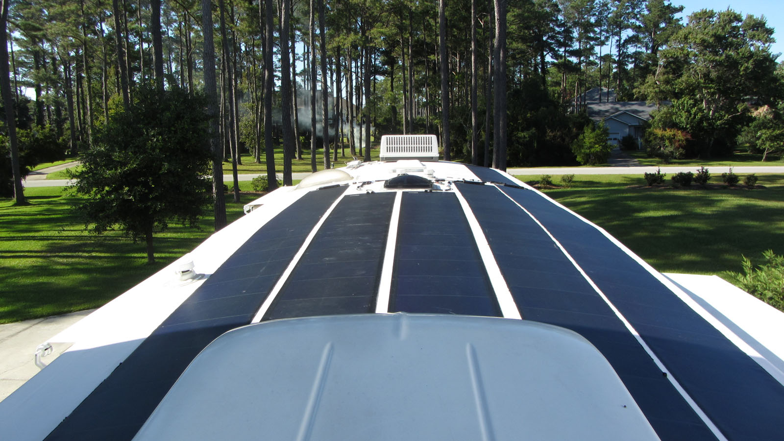
If these panels look different from what you might have expected...
They are!
They are flexible amorphous crystal panels.
They have a peel and stick application method. Once down - they ain't moving.
Without getting technical - these type panels perform better in shaded applications..
Think RV - Forest - Trees.... Shade....
Soon all the panels were down and ready for the final test....

I threw the breakers and my controller lit up and Voila...
We began harvesting energy from the Sun!
All systems are go!

Top Black Gauge is the Inverter Display/Controller
The bottom right is for the Solar Controller.
Fantastic off the grid set up. Similar to our capacity and 2k inverter. You will love having this rig. Congrats on the set up.
ReplyDelete